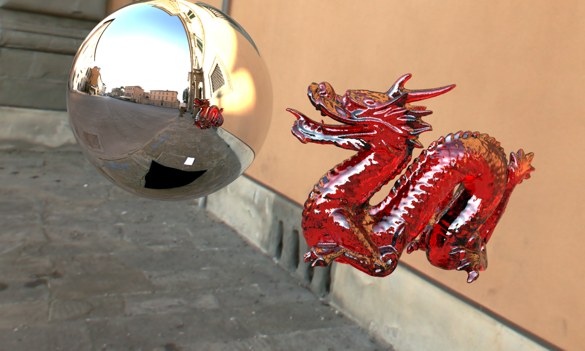
Hello trace-masters!
In my third assignment, my task was to implement those capabilities to my raytracer:
- Transformations (Scaling, Rotation, Translation)
- Instancing
- Distribution Ray Tracing
- Depth of Field
- Motion Blur
- Soft Shadows
- Glossy Reflections
Let’s examine them together!
Apart from those three main capabilities, I have also added those ones:
- .PLY file format parsing for meshes (tinyPLY 2.0)
- Smooth shading of meshes (by interpolating vertex normals using barycentric coordinates)
- Simple camera type, where FovY angle is given instead of image plane L, R, T, B coordinates.
Moreover, I rewrote my refraction code segment from zero over again to simulate glass objects. By doing so, I was able to significantly improve my glass rendering quality (screenshots are provided in between the paragraphs).
Transformations
To implement trasformations, I have added a 4×4 Matrix4 class, so that I could convert the given transformations into their Matrix4 forms, and transform Points and Normals by multiplying them with those 4×4 transformation matrices.
While parsing the input scene file, I push the Transformations of the Mesh in their given order into a std::vector<Transformation> then create the composite M matrix by multiplying those transformations with each other. At the end, each Vertex of each Triangle of the given Mesh is multiplied by the composite matrix M to be put into their world coordinates (actually, this is not a good idea from the point of view of instancing, we will see why at the end of this post).
Many of the scenes provided for this assignment includes Transformations; so, without implementing this capability, meshes would not get placed in front of the camera and no rendering would be done.
Note: One must not forget to convert the provided Rotation angle from degrees to radians, to be able to correctly rotate the shape.
Depth of Field
A nice capability that can easily be implemented is Depth of Field (DoF), which can be used to focus the camera on the object of interest, and blur the rest of the scene according to the distance to the focus point.
By reading the ApertureSize and the FocusDistance from the input file, I have put the image plane FocusDistance far away from the camera, and scaled it by (FocusDistance / NearDistance) times to be able to protect the field of view of the original camera.
Next, I have created a squre aperture, where each edge is in size of ApertureSize, and used the same approach I have used to implement MSAA (Multisample Anti-Aliasing) capability, where NumSamples many ray are send from the camera into random locations of the same pixel on the image plane, but this time sending the rays from random locations of sqrt(NumSamples) x sqrt(NumSamples) Aperture Grid, into the center of the same pixel on the image plane.
By doing so, shapes that are very close to the image plane are put into focus successfully. Below is a GIF file that demonstrates DoF capability by putting each of 4 spheres into focus at different renderings (little black line scatterings are caused by Giphy GIF Maker. They are not included in the real rendered images):
spheres_dof.xml
(800x800) - 4 images
Each ~31 secs (/w 8 thrd, 100 MSAA, DoF)
Motion Blur
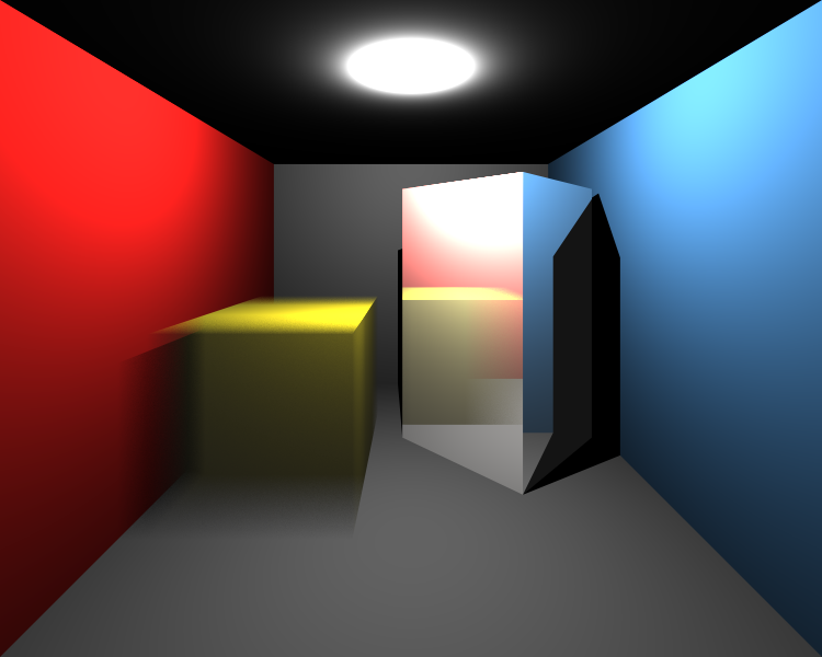
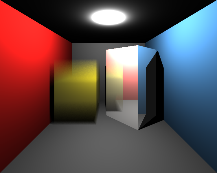
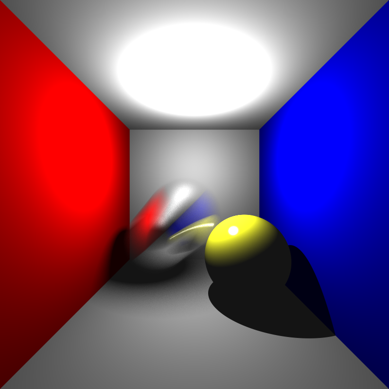
Motion blur (MB) is used to give the effect of movement to the shapes. As the aperture is open for some time interval in a real camera, a moving object gets rendered in blur towards the moving direction.
To simulate this in my ray tracer, I have given each MSAA sample ray of one pixel a random Time variable ranging from [0, 1], and used that time variable to move the ray hit position towards the direction of velocity by multiplying ray.time * hitInfo.material.motionBlurXYZVec if the material hit has motion blur effect.
cornellbox_boxes_dynamic.xml
(800x800)
5 mins 25 secs (/w 16 thrd, 900MSAA, MB)
cornellbox_boxes_dynamic.xml
(800x800)
5 mins 22 secs (/w 16 thrd, 900MSAA, MB)
cornellbox_dynamic.xml
(800x800)
6 mins 46 secs (/w 16 thrd, 900MSAA, MB)
Bounding boxes of the shapes need to be extended to cover all the motion blur distance from time 0 to time 1. In my implementation, as I only have the scene BVH itself -which has Triangles and Spheres in the leaf nodes- and no mesh BVHs, what I did was to extend each leaf node’s bounding box by motionBlur amount. However, this approach put my head in trouble, as for larger meshes that contain millions of triangles (e.g. dragon_dynamic.xml scene), increasing the BBox extents of those tiny triangles dramatically decreased the performance of my BVH searches.
Edit: The original scene with 100 MSAA samples is rendered in 4 hours, 8 minutes, and 37 seconds:
dragon_dynamic.xml
(800x480)
4h 8m 37s (/w 8 thrd, 100 MSAA, MB)
To prevent this problem, each mesh must contain its own BVH in it, and only the most outside BBox of the mesh must be extended to catch the rays in motionBlur distance and test them with the nodes and the leaf triangles of the mesh. If hit is found, then the triangle’s hitInfo.pos must be extended to hitInfo.pos + motionBlurVec. By doing so, not the BBoxes of those millions of triangles are extended, but only the most outside BBox of the mesh is extended. Using this idea would not cause any harm to the BVH search performance.
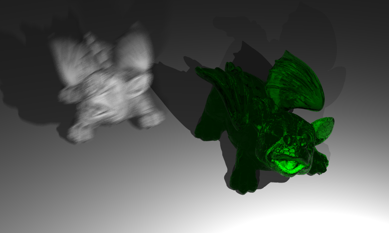
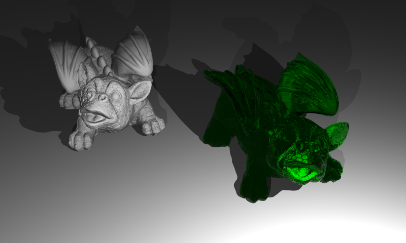
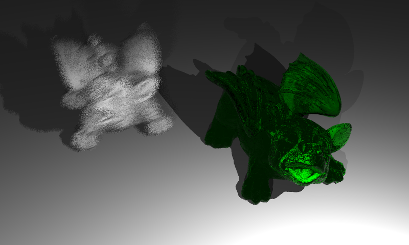
I decreased the NumSamples to 4 for the dragon_dynamic.xml scene to be able to get fast renders. Below is the screenshots without / with motion blur effect, respectively:
dragon_dynamic.xml
(800x480)
18 mins 5 secs (/w 8 thrd, 100 MSAA, no MB)
dragon_dynamic.xml
(800x480)
~11 minutes (/w 8 thrd, 4 MSAA, MB)
Soft Shadows
To implement soft shadows (SS), I needed to parse the light type of AreaLight from the input file. Until that point, my ray tracer have only had PointLight class.
So, I have converted my PointLight class into Light class, and put all light attributes in it, so that I could keep each PointLight and AreaLight input in a Light instance. I check EdgeVector1 and EdgeVector2 to figure out if the current light is an area light or a point light during the ray tracing process.
When checking whether the point is in shadow or not, I sent the shadow ray from the point to a random location in the area of the area light, and multiplied the light intensity with the dot(-shadowRayDir, areaLightNormal) (i.e. cos of the angle between the shadow ray and the area light normal) to arrange that light’s intensity on the hit point.
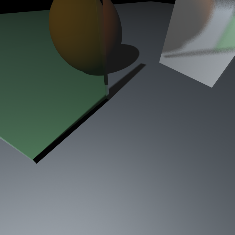
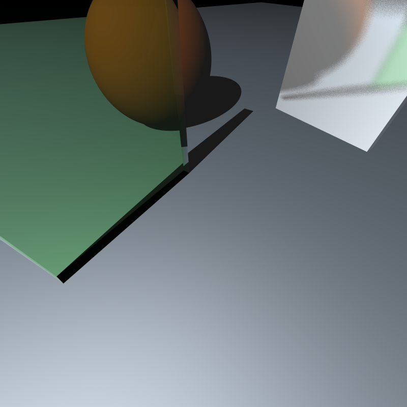
Below is a GIF file that shows the difference between hard shadows and soft shadows by using point lights and area lights, respectively. The brightness difference is caused by the cos(angle) calculation discussed above; point light scene is more bright:
metal_plates_area.xml
(800x800)
36 secs (/w 8 thrd, 36 MSAA, SS, GR)
Glossy Reflections
GR is used to simulate non-perfect, glossy brushed metal surface reflections. It is implemented by perturbing the direction of the reflected ray by a small amount.
First, an orthonormal base is created for the original reflection ray by making its smaller coordinate 1, and using cross products to find the ONB axes. Then, a square area is created by using the Roughness parameter in the input file as the edge length of that square. The reflection ray is then perturbed by -(roughness / 2) + rand(0..1)*roughness amount at each axis. The former term is used to make the original reflection ray pass through the center of that created square for a good perturbation. The perturbed ray is then used as the reflection ray and sent into the scene.
The image provided at the end of the Soft Shadows chapter shows an example of glossy reflections. Below is another image which uses PointLight for the same scene (this is also the second image of the GIF file above):
metal_plates_area.xml
(800x800)
28 secs (/w 8 thrd, 36 MSAA, no SS, GR)
Smoothing
Instead of using the same normal vector for any hit point on a triangle, one can calculate the normal vector of each Vertex of a triangle -by summing up all the normal vectors of the neighbour triangles of that vertex and normalizing the resulting vector-, and use an interpolated version of those 3 vertex normals as the normal vector of the hit point during the Triangle::Intersection routine by using the barycentric coordinates of that hit point.
My current implementation of smoothing calculates the vertex normals in a brute force manner by searching the current vertex among all triangles, for all vertices of all triangles. This causes the initial scene parsing procedure to last ~4 minutes to be able to correctly compute the vertex normals, but the time complexity of the ray tracing part does not get affected when vertex normals are used instead of triangle normals.
Below is a GIF file that shows of how that small change can produce beautiful images from the same input triangle set (flat and smooth shading):
killeroo_glass.xml
(800x800)
Total render time: 5 mins 8 secs
~4 minutes of it to calculate vertex normals
(/w 8 thrd, 16 MSAA, Smooth)
Instancing
Instancing is used to have meshes that use the same base mesh, but have additional transformations, properties, etc.
During the assignment period, I have parsed MeshInstance meshes as if they themselves are Mesh meshes, by duplicating the triangles of the base mesh for the new mesh instance, and got all output renders provided in this post by using this procedure.
When I started the implementation of instancing capability, I figured out that my BVH implementation idea of “1 BVH for only the scene itself, consisting of just triangles and spheres, but not differentiating the meshes.” is a VERY bad idea.
Instancing requires each mesh, mesh instance and sphere to have its own BVH tree, and the scene BVH to point to those inner BVHs, so that when a ray is sent, it could be converted into the local coordinates of each mesh and mesh instance by just multipyling the inverse of the composite transformation matrix of that mesh. When a hitpoint is found, the hitNormal is then multiplied by the inverse transpose of the composite transformation matrix of the mesh to convert it into world coordinates. Hitpoint parameter t stays the same in both coordinate systems; and the direction vector of the main ray should not be normalized for this coordinate space conversion to work.
I have used late days for my assignment to be able to successfully implement instancing capability. I have implemented the ray conversion system from world coordinates to local coordinates for Intersection routines, and built BVH for each mesh, mesh instance (points to the BVH of the base mesh, but it has its own composite transformation matrix), and sphere. The rays are sent to the BVH of each mesh, mesh instance and sphere in a loop; so, the scene itself do not contain a BVH.
However, when the ray tracing process that use instancing begins, I get segmentation fault error when the leaf nodes’ Intersection routines are launched during a Ray & MeshBVH intersection traversal. I am currently working on this bug, when I solve it, I would be able to use instancing correctly in my next assignments.
What’s next?
Along with my next homework tasks, I will also:
- Debug and correct my instancing code, so that I could use instancing in a memory-friendly manner.
- Improve the performance of Motion Blur BBox calculations by using instancing.
- Shorten the time complexity of the smoothing process by implementing a different method which does not require traversing the vertices again and again.
- Extend .PLY parser to parse x, y, z vertex coordinates given without nx, ny, nz coordinates (buddha.ply). Currently supporting x, y, z, w quadliterals and x, y, z, nx, ny, nz six-tuple triangle representations.
Hope to see you in the next part!
Happy tracing!
