Hey trace-masters, High Dynamic Range rendering is here!
In my fifth assignment, my task was to implement:
- HDR (High Dynamic Range) rendering capability, which includes
- Exporting images as .exr files, and
- Performing tonemapping operation to map HDR images to LDR (Low Dynamic Range), so that their approximate appearances can be shown on non-HDR screens.
- Two new light types, which are
- Directional light
- Spot light
In this post, we will examine them together!
Directional Light
Directional light does not have a position, but a fixed direction and radiance value defined to be used at any place inside the scene. When light calculations are being done during ray tracing process, the radiance value of the light is used without any attenuation; and shadow ray directions are calculated by simply negating the direction value of the light.
Below are my outputs:
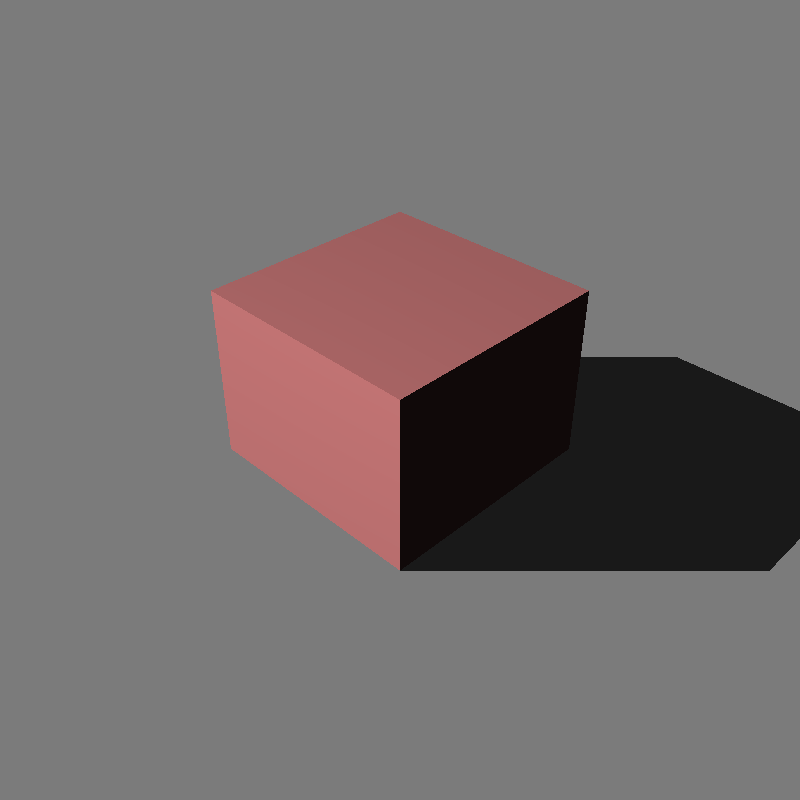
cube_directional.xml
(800x800)
/w 8 thrd, no MSAA
1 cube, scaled to x2.
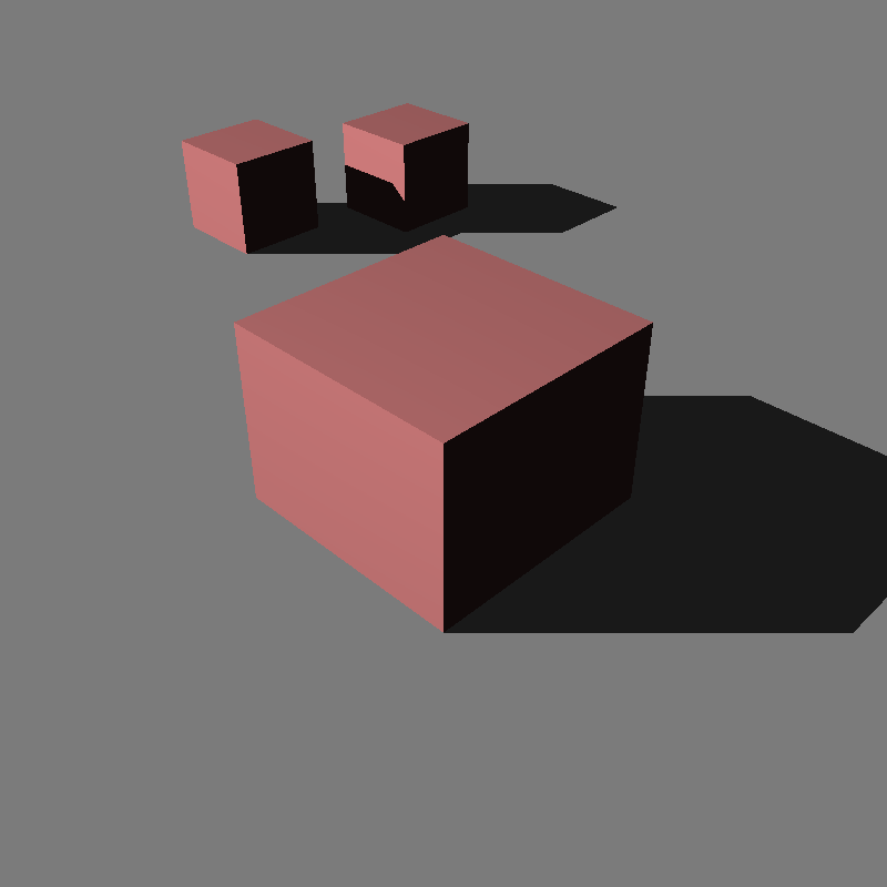
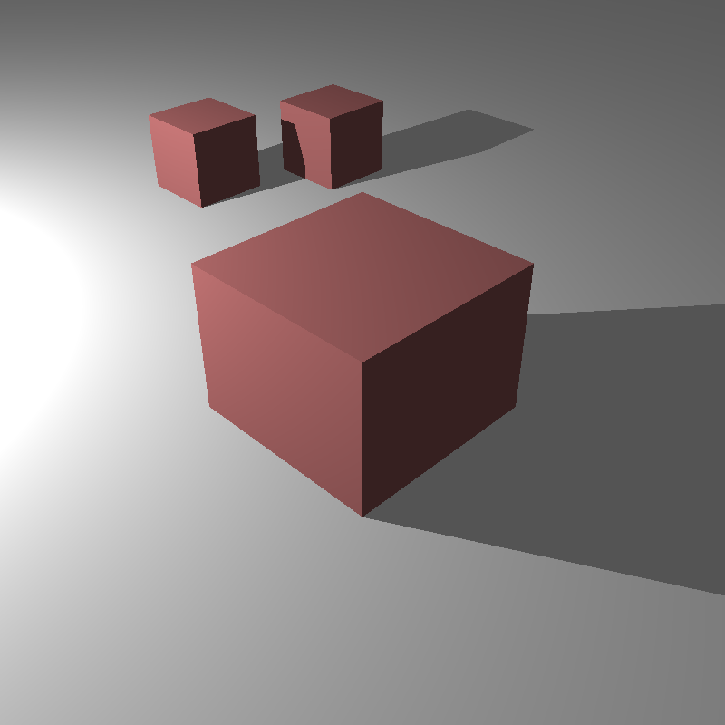
cube_directional.xml
(800x800)
/w 8 thrd, no MSAA
3 cubes, closer one is scaled to x2,
Further ones are not scaled.
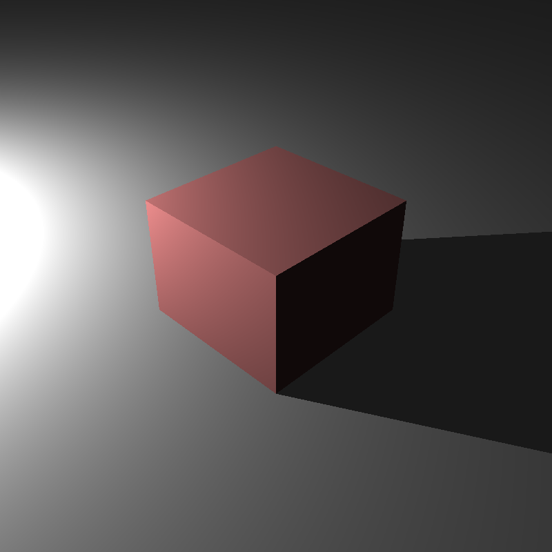
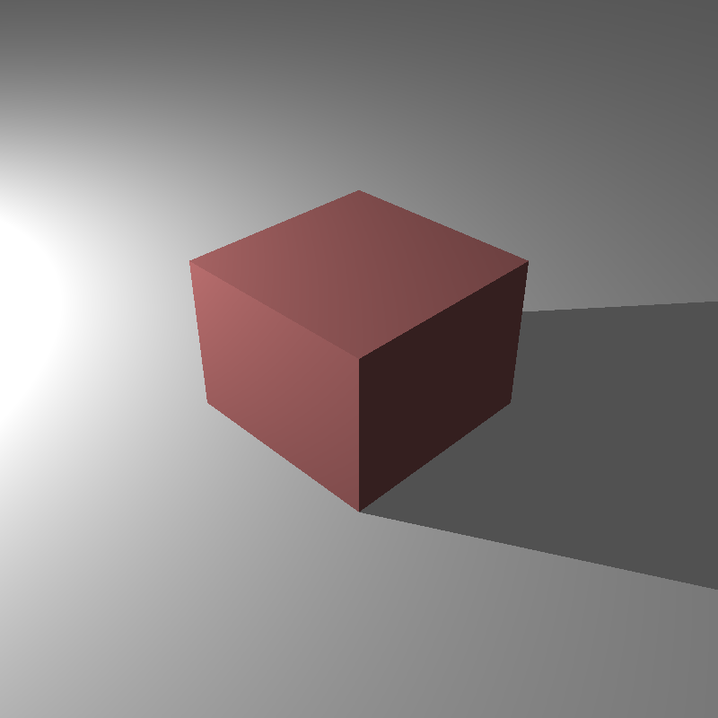
Below is the output of the same scene, but this time using a Point Light:
Spot Light
Spot light have CoverageAngle and FalloffAngle values defined in addition to position, direction and intensity values. CoverageAngle defines the angle in which the area under it will be lit. FalloffAngle defines the angle after which the intensity of the light starts to decrease in a non-linear fashion until CoverageAngle is reached. That non-linear decrease provides a nice transition between the area lit and the area unlit.
I think Spot Light is the coolest light type among the light types we’ve encountered so far. By checking my output images below, you will understand why I think so:
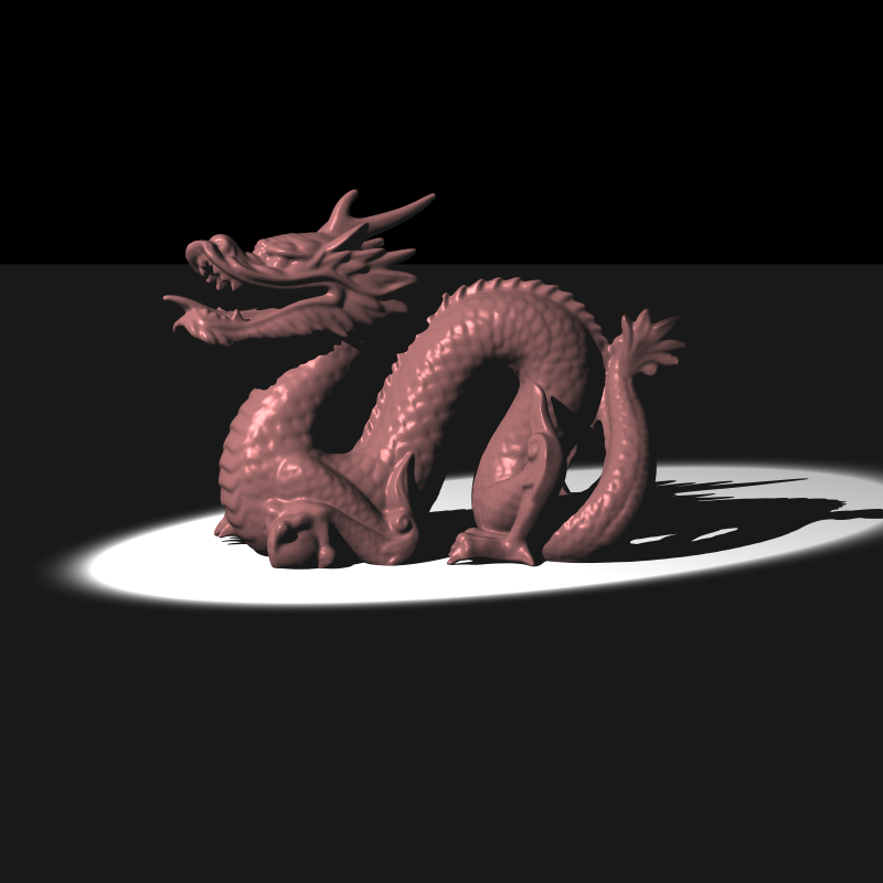
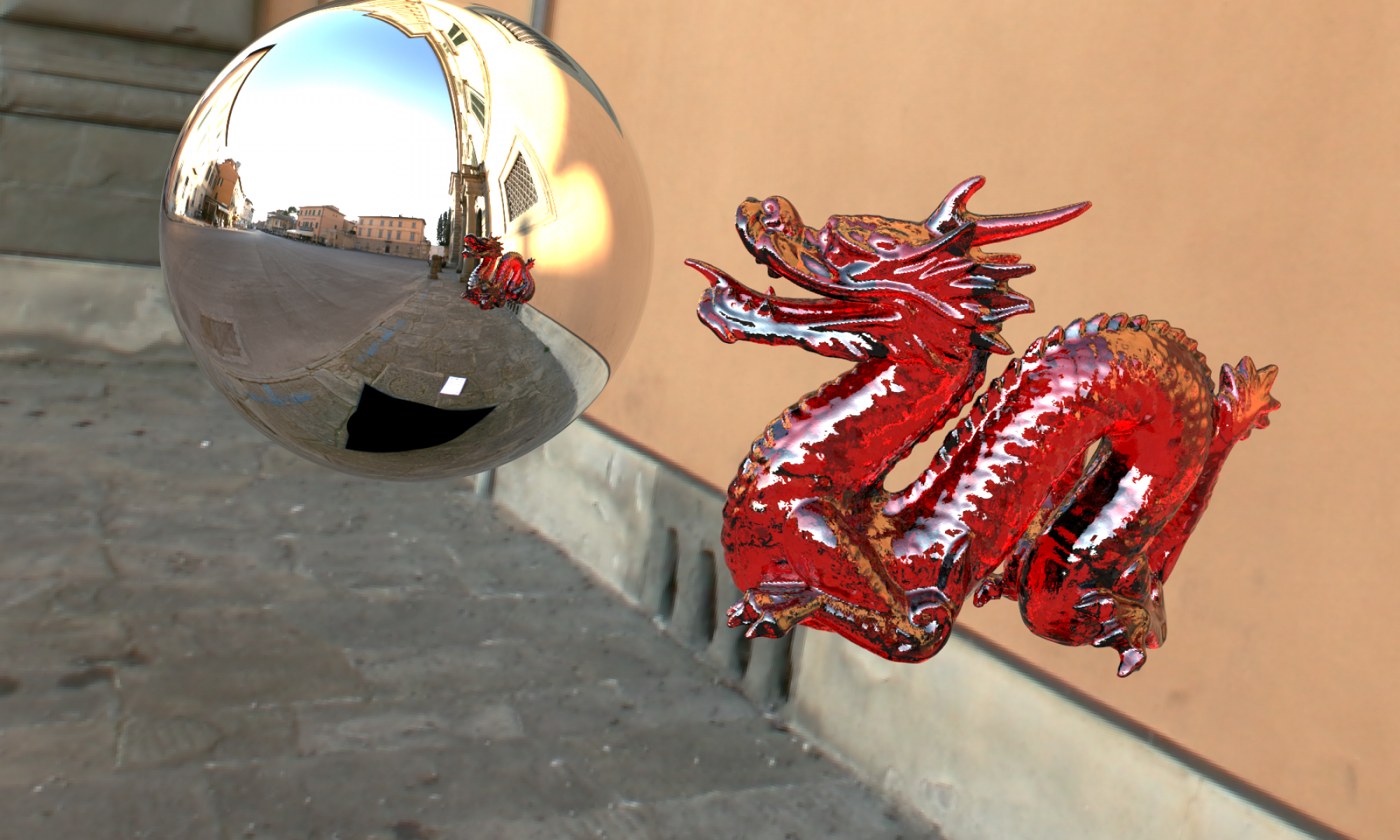
dragon_spot_light_msaa.xml
(800x800)
/w 8 thrd, 100MSAA
CoverageAngle: 10
FalloffAngle: 8

dragon_spot_light_msaa.xml
(800x800)
/w 8 thrd, 100MSAA
CoverageAngle: 16
FalloffAngle: 13
Rendering HDR Images and Exporting them in .exr format
In the previous version of my raytracer, I was clamping the total color value to 0-255 interval to be able to output the final image in .png format. Just by deleting these clamping codes, my raytracer were ready to output in .exr format.
I have used the tinyexr library to be able to output in .exr format. Then I have used exrdisplay tool to visualize that rendered HDR image.
You can visualize my two .exr outputs by following the links below (move the handles of the slider to right step by step, while “Gamma 2.0” option is selected):
- 1_cube_no_degamma.exr (1 cube, no cube degamma)
- 3_cubes_no_degamma.exr (3 cubes, no cube degamma)
- 1_cube_degamma.exr (1 cube, cube degamma)
Tonemapping
We have used Photographic tonemapping operator to map HDR output to LDR 0-255 .png file. I have implemented the operations explained both in the lecture and in the paper to produce the LDR output.
Below are my tonemapped outputs:
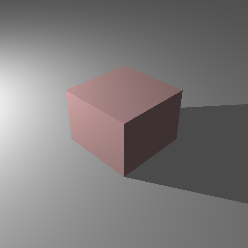
cube_point_hdr.xml
(800x800)
/w 8 thrd, no MSAA, Photographic Tonemap,
No Cube Material Degamma,
1 cube.
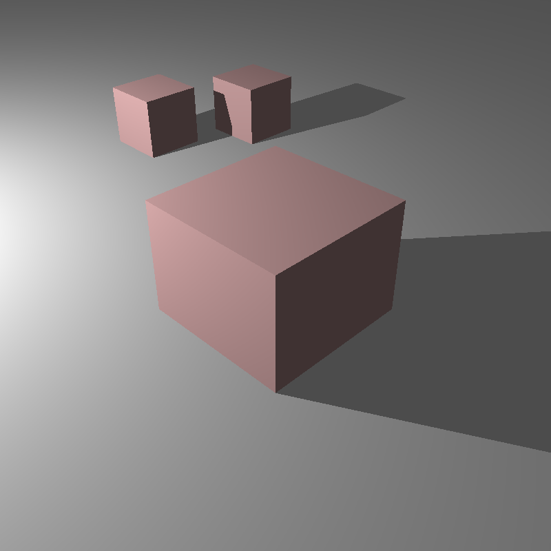
cube_point_hdr.xml
(800x800)
/w 8 thrd, no MSAA, Photographic Tonemap,
No Cube Material Degamma,
3 cubes.
cube_point_hdr.xml
(800x800)
/w 8 thrd, no MSAA, Photographic Tonemap,
Cube Material Degamma,
1 cube.
cube_point_hdr.xml
(800x800)
/w 8 thrd, no MSAA, Photographic Tonemap,
Cube Material Degamma,
3 cubes.
Hope to see you in the next post!
Happy tracing!